


|

|
|
Test Sections Available for Three-Phase Flow Loop
In the indoor three-phase flow loop, four test sections are available. These are briefly described below.
- Hydrodynamic LLCC Test Section
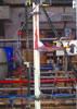 This is a 2-inch I.D. 80-inch tall facility, as shown in the linked figure. The oil-water mixture flows into the LLCC through a 25-degree downward inclined tangential inlet of 2-inch ID, located 44 inch below the top of the LLCC. The mixture is split into two streams, the oil overflow stream and the water underflow stream. The flow rate in each stream is controlled manually using the two valves located downstream of the LLCC. The flow rates and water cuts are measured with several Micromotion mass flow meters. This is a 2-inch I.D. 80-inch tall facility, as shown in the linked figure. The oil-water mixture flows into the LLCC through a 25-degree downward inclined tangential inlet of 2-inch ID, located 44 inch below the top of the LLCC. The mixture is split into two streams, the oil overflow stream and the water underflow stream. The flow rate in each stream is controlled manually using the two valves located downstream of the LLCC. The flow rates and water cuts are measured with several Micromotion mass flow meters.
- GLLCC Test Section
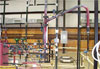 The GLLCC, shown in the linked figure, is a 3-inch 8-ft pipe, similar to the GLCC, but used for separating gas/oil/water flow. It has three outlets: The gas is removed from the top, while the oil and the water mixture flows to the bottom. Due to the centrifugal forces, the oil moves to the center. A special 1-inch oil finder is provided at the center of the GLLLC to remove the oil, while the water is removed tangentially from the bottom. The flow and water cut measurements and the control of the flow in the different streams are done in a similar manner used for the LLCC. The GLLCC, shown in the linked figure, is a 3-inch 8-ft pipe, similar to the GLCC, but used for separating gas/oil/water flow. It has three outlets: The gas is removed from the top, while the oil and the water mixture flows to the bottom. Due to the centrifugal forces, the oil moves to the center. A special 1-inch oil finder is provided at the center of the GLLLC to remove the oil, while the water is removed tangentially from the bottom. The flow and water cut measurements and the control of the flow in the different streams are done in a similar manner used for the LLCC.
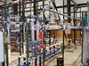
- LLHC Test Section
 This facility includes a Modular Production Equipment/NATCO 2-inch Hydro-swirl hydrocyclone as shown in the linked figure. Particle size distribution upstream of the LHC will be analyzed using a CILA analyzer capable of measure particles from 0 to 192 mm. The sample will be taken using an iso-kinetic sampler, and a surfactant will be added to the sample in order to keep the particle size distribution constant during the analysis. This facility includes a Modular Production Equipment/NATCO 2-inch Hydro-swirl hydrocyclone as shown in the linked figure. Particle size distribution upstream of the LHC will be analyzed using a CILA analyzer capable of measure particles from 0 to 192 mm. The sample will be taken using an iso-kinetic sampler, and a surfactant will be added to the sample in order to keep the particle size distribution constant during the analysis.
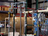
- Horizontal Pipe Separator (HPS) Test Section
 The HPS is based on a simple concept, in which a horizontal pipe spool with appropriate geometry promoting the natural separation of the phases is utilized. Optimal design of the pipe separators can replace vessel separators, decreasing costs and simplifying installation and operation. It could be very effective for separating oil dominated flows. As shown in the linked figure, it consists of a 4-inch horizontal pipe section, equipped with mass flow meters located upstream and downstream. The oil-water flow into the HPS is mixed at a mixing-T and a static mixer. The inlet and the outlet pipes are 2 inch in diameter. Experiments are conducted to develop mechanistic model by measuring the liquid level, droplet size distribution and evaluating the separation efficiency at stratified flow conditions. The HPS is based on a simple concept, in which a horizontal pipe spool with appropriate geometry promoting the natural separation of the phases is utilized. Optimal design of the pipe separators can replace vessel separators, decreasing costs and simplifying installation and operation. It could be very effective for separating oil dominated flows. As shown in the linked figure, it consists of a 4-inch horizontal pipe section, equipped with mass flow meters located upstream and downstream. The oil-water flow into the HPS is mixed at a mixing-T and a static mixer. The inlet and the outlet pipes are 2 inch in diameter. Experiments are conducted to develop mechanistic model by measuring the liquid level, droplet size distribution and evaluating the separation efficiency at stratified flow conditions.
|
|

